Blue Basic detectors PCB 22.x:
Detector boards with circuit diagrams, board layout and bill of materials (eagle.sch, eagle.brd, gerber, exel format)
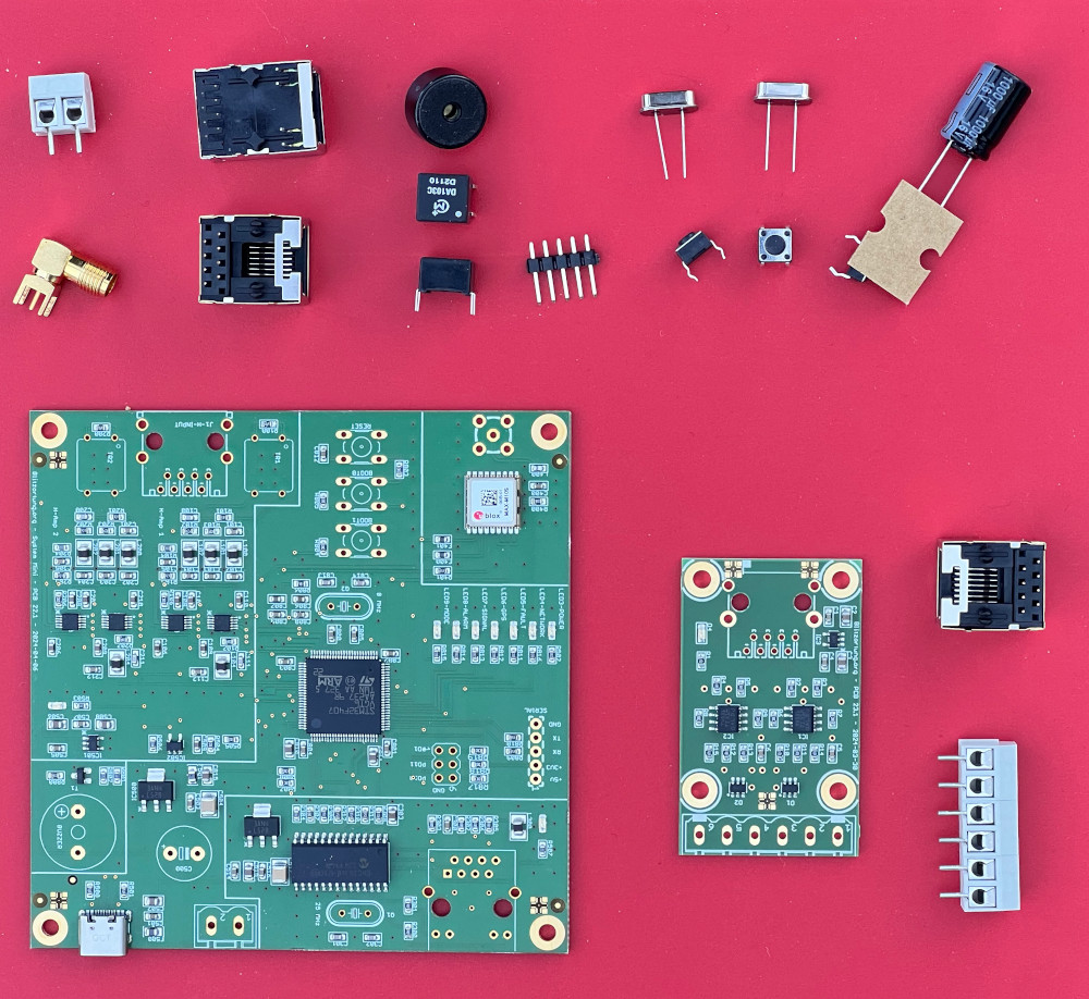
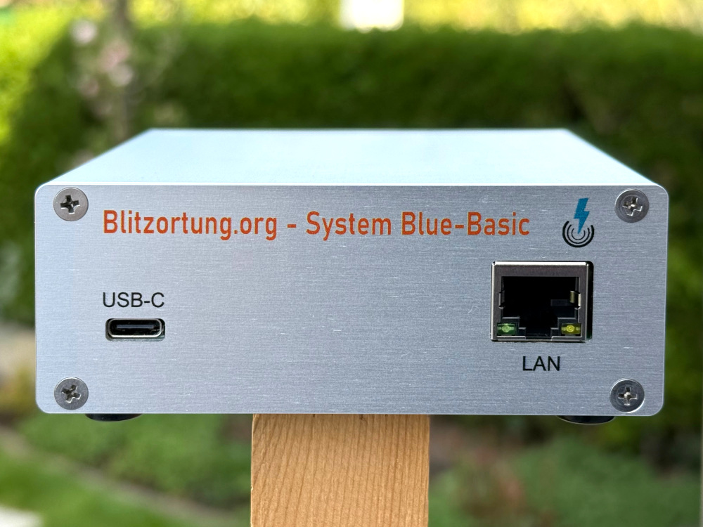
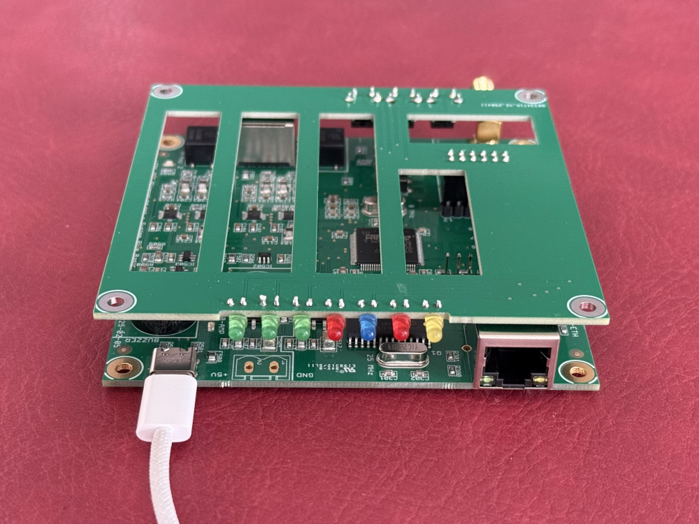
- The RJ-45 HanRun socket with the LEDs is the socket for the Ethernet connection to the router. The other RJ-45 socket without the LEDs is the socket for the connection to the preamplifier. Please do not swap the connections. This may cause a defect in the LP5907MFX-4.5NPB / IC503 voltage regulator on PCB 22.0/1/2.
- You can power the board either via the USB-C socket or via the 2-pin terminal block. The C500 electrolytic capacitor (560µF – 1000µF) is only necessary if you're using a dirty power supply or if the board is powered via the terminal block. Do not solder this capacitor if you're using a smart USB-C power supply, such as those used to charge laptops. These power supplies can classify the detector as a voltage source if there's a residual voltage on the capacitor.
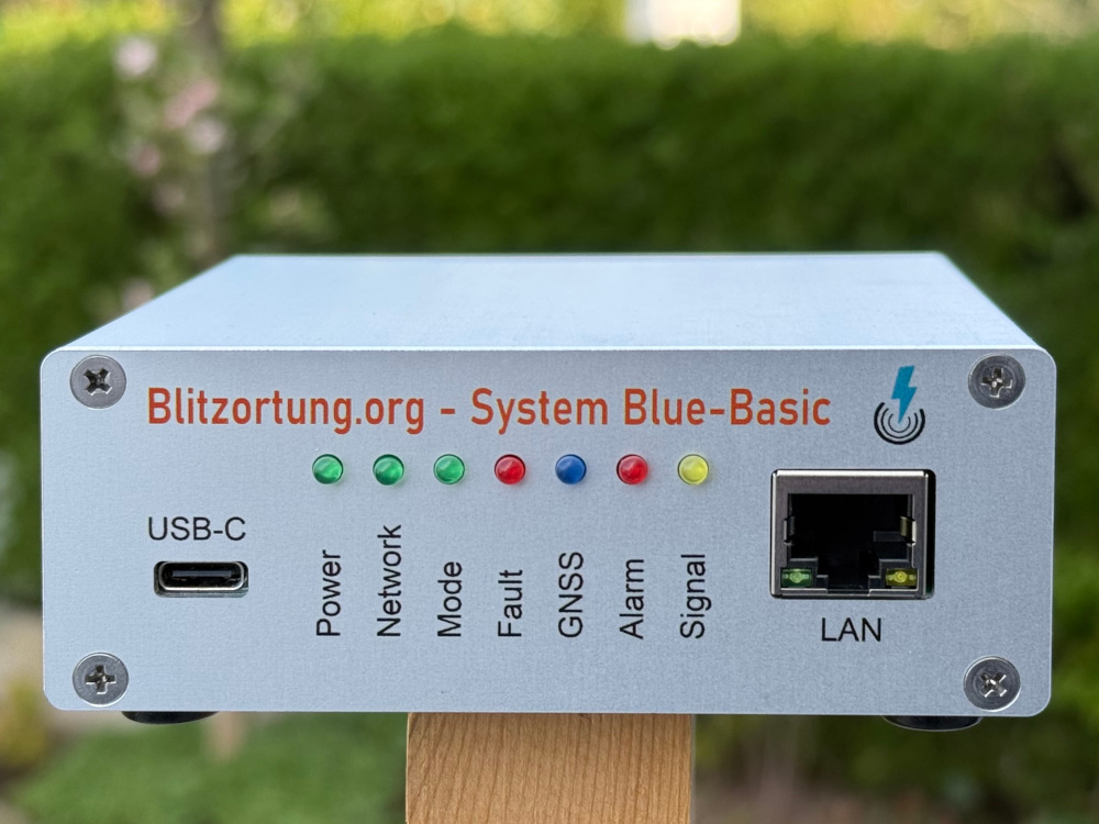
- If you cannot find the detectors IP address in your router (look for “blitzortung”), then you can also get the last number of the IP V4 address acoustically, see the documentation.
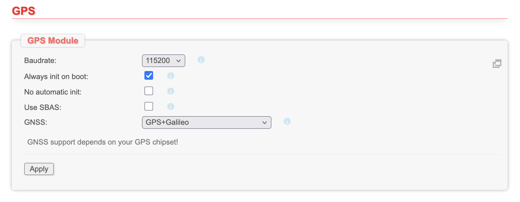
- On the webpage of the Firmware you should set the GNSS type in the "Settings -> GPS" field to "GPS+Galileo". The Baudrate will change to 115200.
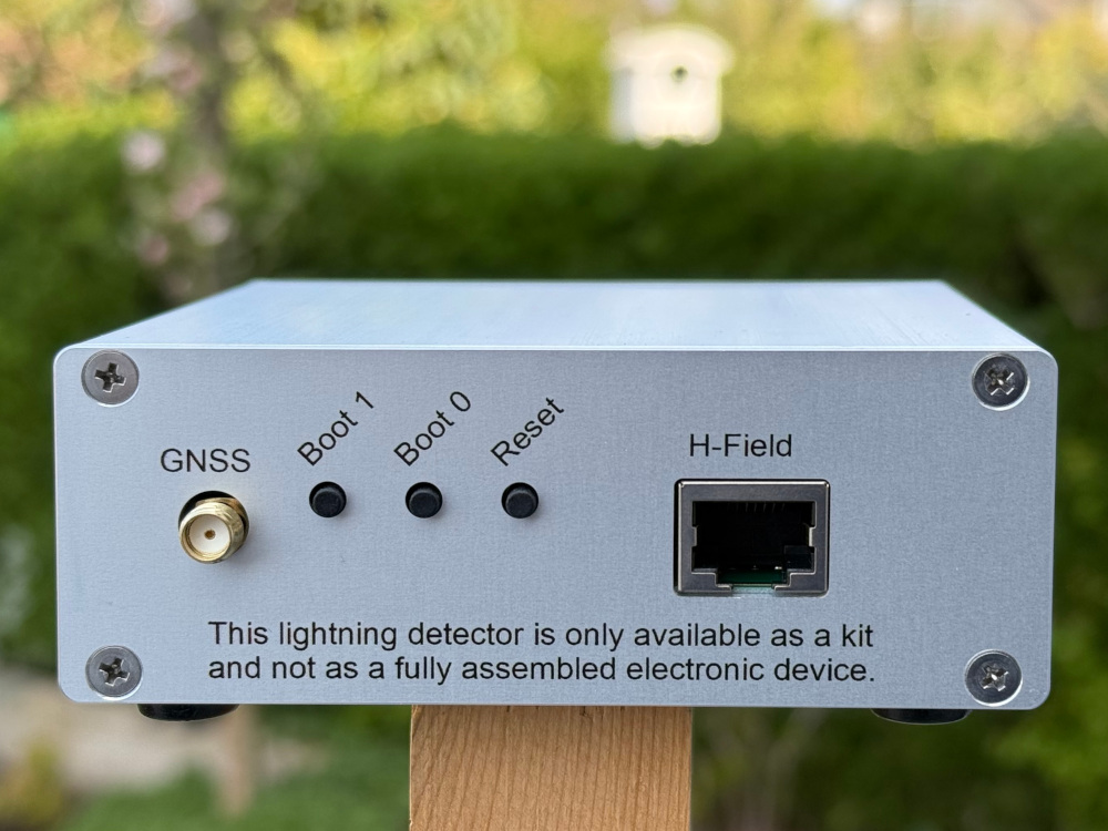
- If you have one of the test boards 22.0/1, then please do not change the jumper settings, these are for selecting different power supply options for some components and for the coding of the board.
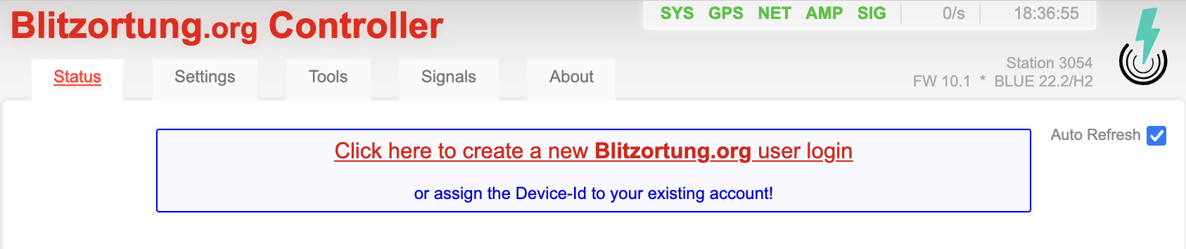
- The link for creating an account at blitzortung.org is above on the first page of the firmware. This link is only shown, if the station is not already assigned to a user. Please do not create a new user account if you already have one. You can assign all your detectors to the same user account.
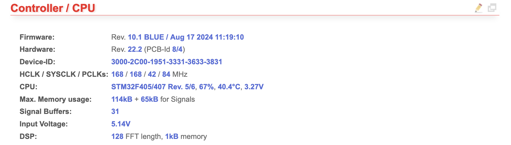
- You will find the Device-ID of the detector in the "Status -> Controller /CPU" field. With this ID you can assign the detector to your user account on blitzortung.org "Project Area -> user data". The minus signs can be omitted.
- It could be that the assignment of the detector to the regions is not correct, because the boards were initially already online in Europe for the initial firmware programming. Please contact me in these cases (blitzortung@gmx.org) if the regions do not change automatically.
-
Please also take a look at the documentation.
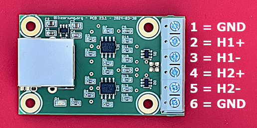
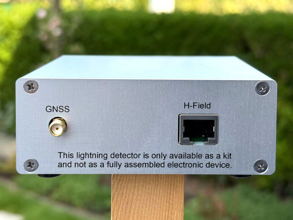
The H-field preamplifier PCB 23.1 has 6 input pins. The two outer pins, pin 1 and pin 6, are ground. They can be used for shielding antennas. Pin 2 and 3 is the first amplifier input, pin 4 and 5 is the second amplifier input.
The enclosures:
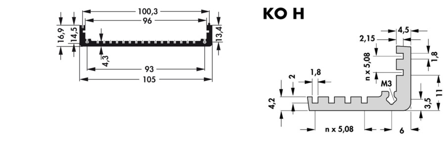
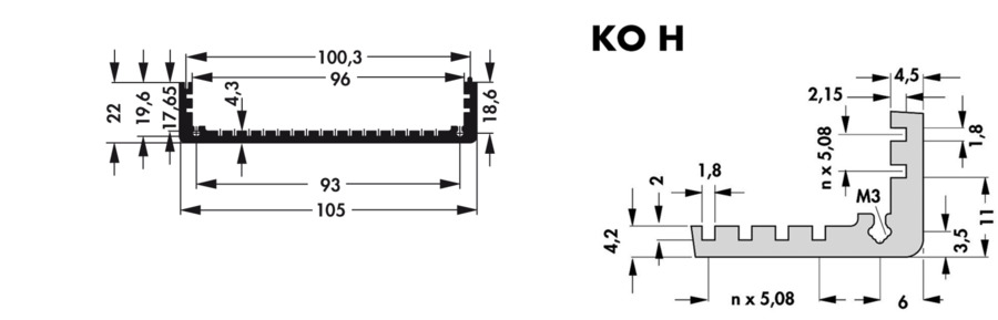
The PCB 22.x boards have dimensions of 100 mm x 100 mm and can therefore be easily installed in standard enclosures. For the profile enclosures from fischer elektronik, which are assembled from the two housing shells KOH 1 100 (100 mm x 105 mm x 16.9 mm) and KOH 2 100 (100 mm x 105 mm x 22 mm), we offer prefabricated front panels and back panels in the size of 100 mm x 38.9 mm.
Firmware update:
For Blue Basic, use the firmware for System Blue. Firmware version 10 contains new automatic update feature. In case of a new firmware release the controller itself can download the firmware file from the server. After that the downloaded firmware will be verified and can be written to the flash. Both, download and flashing can be triggered manually by you or by the server.
Automatic updates help us to hold the whole network up to date. Station owners don't have to care about checking for new firmwares and installing them.
Installation of a detector:
You can either set up the hardware yourself or have it built up by others. However, if you would like to order the partially built hardware from us, please note the information in the following order list.
Connecting the ferrite rod antennas:
The connecting wires of the ferrite rod antennas are varnished. Please scrape off the varnish from the connecting wires and solder a short, thicker wire to the thin wires. This allows you to clamp the wires firmly with the screw terminals. The knot on one of the connecting wires of the ferrite rod antennas is irrelevant for our preamplifiers. This is the wire end under the winding. The winding was therefore wound over this cable. The plus (+) and minus (-) markings are also irrelevant for our purposes. The new 23.1 preamplifiers have balanced inputs. Connect one of the H-field antennas to the two contacts H1(+)/H1(-) and the other H-field antenna to the contacts H2(+)/H2(-).
Finding the best position:
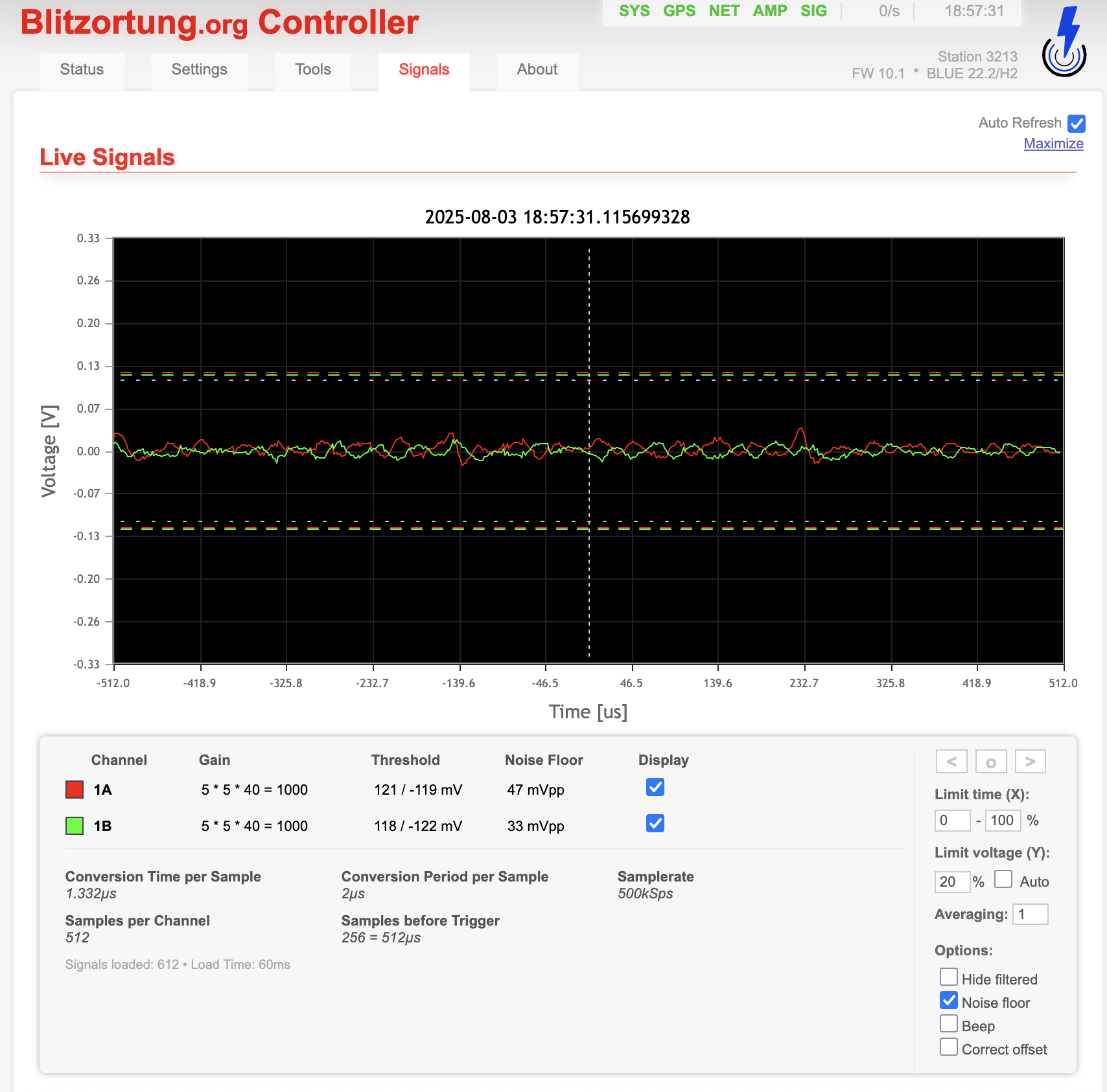
Set the "Noise floor" option on the signals page and monitor the live signal. Move the antennas until you see a signal that is as free from interference as possible.
The current order list: